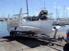
Floats are painted with a Hi-Build filler and stored for assembly with the mainhull and beams later.
 My first plan was to finish paintjob now but I find that it may be easier to do float together with beams when they are joined together.
 Floats are painted with a Hi-Build filler and stored for assembly with the mainhull and beams later.My first plan was to finish paintjob now but I find that it may be easier to do float together with beams when they are joined together.
 Central mounting modules (CMM) are now ready to fit in the coming mainhull. On wood blocks added the arms will sit .
 I just got hold of a Marstrom carbon mast, only problem is that it is in two parts. I should be able to join the pieces where the spreaders will be.
  Profile is 210X 90mm.
 As seen here the bottom is fine. The ball socket is also there, I just remove it for further reinforcement.
 Forestay attachment is ok but the spinnaker is too low. Don't know if the u -bolt are for 2:1 hailyards. Anyone??
 First a jig is build.
 In center is the recess for upper folding strut (UFS).
 The surplus of the chipboard is used to for another jig used for making upper corner and the top of the beam.
 The corners are heat formed as described earlier on this blog (see floats).
 A flange is formed. More on this later.
 I have to do this for 4 beams as with all processes when building your own beams.
 Also these parts will be needed. Fiber bearings for UFS. ( why is the circles carbon? Because I had a nice pro-made piece at hand, thats why!)
 Here I made a full scale model of my idea. Board up.
  And down. The original board is also seen
 F 35 board. It is sticking up higher than normal. Mast raising is done ether on the water or using a special u shaped gin pole.
 Laying up the ply and reinforcement. Black band is a double 300 g/m Uni carbon, both sides.
 After cure. Mold visible under part. This is just some chipboards with plastic tape. Used a crowbar to release!!!!
 Film and bleeder to the garbage. ( delivered to waste deposit as paint to be destructed)
 More carbon after joining the two parts. Also see Rogers F22 Page for more info.
 Port side. Hole for down block screws set from inside glassed over. Inside is painted with epoxy added graphite powder. I will paint anti-foil later.


 To assembly the CMM bulkhead and the solid glass plates, I built a jig. This is my idea since Building book gives no details of how to do this. But it is very important that the holes lines up and are at the right distance. The jig consist of a base with two right angle alignment plates. The one to the right is screwed to base, the other is not. Two ply bricks of 8 mm height keeps the bulkhead up, see pictures below.
 The part are glued.

 Bulkhead is ready for the next assembly. This is not the right bolt here, just to illustrate what this is about.
 More jigs is needed, first an assembly jig, for the complete CMM.
 Next another right angle to hold bulkhead in position.
 Glass plates fits into topplate.
 As well as end plates.
 Now pushed against jig that will set different plates in correct angles. All CMM ends must be the same.
 Alignment lines should match up with top plate.
 Bolt plates of solid glass.
 Bogging and fillets all joints.
 Using a mouth examine stick to smooth fillet.
 Poor Saddam H.
 Taping is done, and removed from jig, (remember package tape on jigbase !!)
 More panels are made, this time core is 6 mm plywood, used for CMM parts and for beam recesses later.
 Jorn is making a pleat in the vacuum bag.
 Vacuum being applied.